IN DESIGN PATENT DRAWINGS, WHEN ARE LINES LINES, AND WHEN ARE LINES NOT LINES?
On December 14, 2020, the U.S. District Court for the Northern District of California handed down a Claim Construction Order for 2 design patents that raised the interesting question: when is a line not a line?
The case is simplehuman, LLC v. iTouchless Housewares and Products, Inc. (4:19-cv-027-HSG). The two design patents in play were D644,807 and D729,485. Since the issue is the same in both design patents, it will suffice to use one as an example. Following are Figs. 1-4 from D644,807:

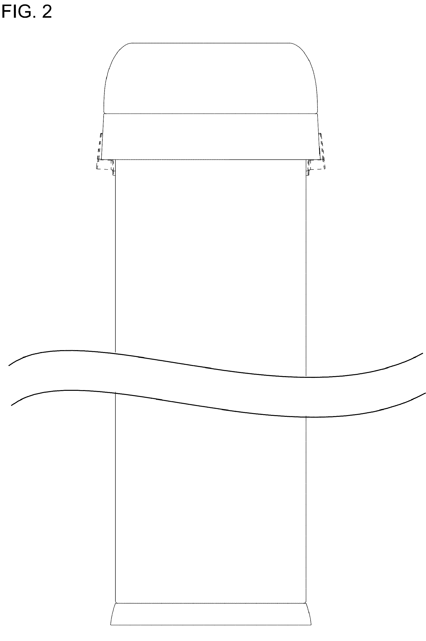


The patentee simplehuman took the position that the various lines in question were contour lines; the accused infringer said they were “seams”, i.e., ornamental features that would need to be taken into account in determining infringement. The court created an annotated version of Figure 1 to “point out the disputed lines” of the ‘087 claimed trash can:

I’m guessing here (ha), but I’ll bet that the defendant’s product is devoid of such lines! To any design patent practitioner the lines in question are so clearly contour lines as to be beyond debate. They are commonly referred to as CAD lines or wire frame lines. Such lines do not generally comply with the USPTO’s drafting rules (time to update those?). Nevertheless, the USPTO routinely accepts drawings with such lines, because everyone knows that they represent contour and cannot possibly be ornamental features. The patentee nevertheless made a mistake in not having its draftsman either remove those lines entirely and/or replace them with standard shading before filing.
Another (practical) reason to remove those lines is that the resulting claimed design will look more like an actual product, rather than a confusing mess. A properly drawn product will be more easily compared to an accused design, especially by a jury.
The court said that the dispute in this case is resolved by the specification, saying “The illustrations in the design patents show the disputed lines in views where they cannot possibly represent shading.” This is the court’s logic:
1. The disputed lines occur on the right side of the trash can (see Fig. 1).
2. The top view of the trash can (Fig. 4) suggests an oval shape where the right side is largely flat.
3. Fig. 2, the front view, confirms the general flatness of the right side.
4. But Fig. 3, the right side, includes the disputed lines around the center.
The court is correct about all four of its observations (but for the “But”). How does that logic result in the disputed lines being called lines and not contour lines? Beats me.
Again, any experienced design patent practitioner knows that those lines represent areas where the underlying surface changes from straight to rounded. Standard stuff.
The court actually admitted that:
“At most, the disputed lines thus represent a delineation between rounded and flat surfaces.”
The court then discounted what it just said: “[T]hat does not suffice to show contour because it does not indicate which surface is receding (because it is curved) and includes lines in views where there would be no contour differences (the top down views).”
Interpretations to the previous quote welcome; feel free to post a comment to this blog.
Bottom line? Take out those damn CAD/wire frame lines before filing. And if there’s any doubt about the shape of the resulting design, have your draftsman insert some standard surface shading.
Simple, humans, right?